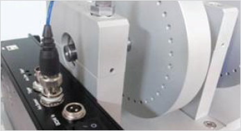
The Machine Black Box (MBB) is a device set apart from conventional monitoring systems by its ability to provide standalone measuring, analysis, diagnostics, display, and network functions.
The product can easily be installed on key equipment to provide round-the-clock symptom analysis and take action against potentially critical equipment faults before they occur. The product displays vibration levels and provides spec management, with programmable time and frequency error judgment codes to allow for configuration to suit user circumstances.
| Item | Function | Explanation | |
|---|---|---|---|
| MBB H/W |
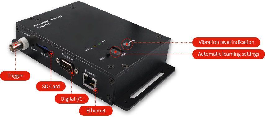
Status LED | Indicates status of value being measured using colors |
|
| Lvel 7-Segment | Data acquisition status display, Input range display, Display of mode depending on pressing of CMD button |
|
|
| CMD Button | Input range indication, LED reset (Green) and mode transition depending on duration of press |
|
|
| Digital I/O Connector |
Trigger signal input and LED status output |
|
|
| PC control program |
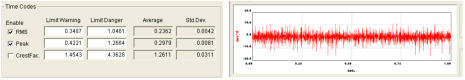
Time Codes | Time domain Test setting |
 |
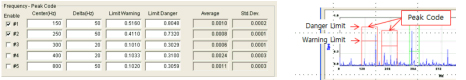
| Frequency Peek Code |
Frequency domain Peak test setting |
 |
|
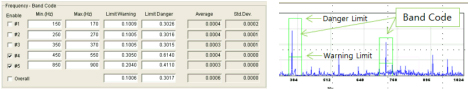
| Frequency Band Code |
Frequency domain Band test setting |
 |
|
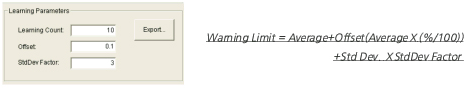
| Learning Parameters |
Learning count and user-defined value settings |
 |
|
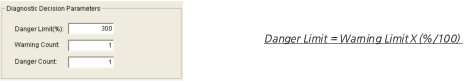
| Diagnosis Decision Parameters |
Danger reference value and consecutive event count setting |
 |
|
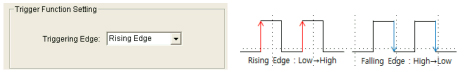
| Trigger Function Setting |
Select signal detection type when measuring through external signal input |
 |
|
| MBB H/W | |
|---|---|
| Function | Status LED | Indicates status of value being measured using colors |
| Explanation | |
|
|
| MBB H/W | |
| Function | |
| Lvel 7-Segment | Data acquisition status display, Input range display, Display of mode depending on pressing of CMD button |
|
|
| MBB H/W | |
| Function | |
| CMD Button | Input range indication, LED reset (Green) and mode transition depending on duration of press |
|
|
| MBB H/W | |
| Function | |
| Digital I/O Connector | Trigger signal input and LED status output |
|
|
| PC control program | |
| Function | |
| Time Codes | Time domain Test setting |
|
|
|
| PC control program | |
| Function | |
| Frequency Peek Code | Frequency domain Peak test setting |
|
|
|
| PC control program | |
| Function | |
| Frequency Band Code | Frequency domain Band test setting |
|
|
|
| PC control program | |
| Function | |
| Learning Parameters | Learning count and user-defined value settings |
|
|
|
| PC control program | |
| Function | |
| Diagnosis Decision Parameters | Danger reference value and consecutive event count setting |
|
|
|
| PC control program | |
| Function | |
| Trigger Function Setting | Select signal detection type when measuring through external signal input |
|
|
|
Test code
-
Time Signal
-
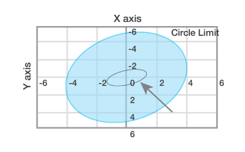
Vibration Orbit
-
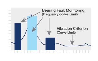
Frequency Spectrum
Example of implementation
-
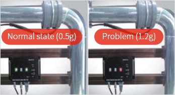
Pipe vibration monitoring
-
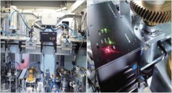
Equipment vibration monitoring
-
Rotation axis vibration monitoring
| Item | Spec | Remarks | |
|---|---|---|---|
| Mechanical | Size(mm) | 164(W)X101(H)X33(D)㎣ | |
| Weight | About 530gf | ||
| Material | Aluminum | ||
| Fix | M5 Bolt-secured | ||
| Electric | Main Power | 24V DC | |
| CPU | TMS320F28335 | ||
| Channel | ICP 1ch | DC transforming capable | |
| Trigger | 3~24V DC | ||
| I/O | Normal, Warning, Danger Output | 9Pin Connector | |
| Communication | USB | ||
| Sensor | Sensor | 10kHz, ICP type Accelerometer | |
| Cable | Military 2Pin to BNC 10m | ||
| Measuring | Acceleration Range | 0.01~30g | |
| Dynamic Range | 90dB | ||
| Frequency Span | 1024Hz, 2048Hz, 4096Hz | ||
| Frequency Resolution | 1Hz, 2Hz, 4Hz | ||
| Mechanical | ||
|---|---|---|
| Item | Spec | Remarks |
| Size(mm) | 164(W)X101(H)X33(D)㎣ | |
| Weight | About 530gf | |
| Material | Aluminum | |
| Fix | M5 Bolt-secured | |
| Electric | ||
| Item | Spec | Remarks |
| Main Power | 24V DC | |
| CPU | TMS320F28335 | |
| Channel | ICP 1ch | DC transforming capable |
| Trigger | 3~24V DC | |
| I/O | Normal, Warning, Danger Output | 9Pin Connector |
| Communication | USB | |
| Sensor | ||
| Item | Spec | Remarks |
| Sensor | 10kHz, ICP type Accelerometer | |
| Cable | Military 2Pin to BNC 10m | |
| Measuring | ||
| Item | Spec | Remarks |
| Acceleration Range | 0.01~30g | |
| Dynamic Range | 90dB | |
| Frequency Span | 1024Hz, 2048Hz, 4096Hz | |
| Frequency Resolution | 1Hz, 2Hz, 4Hz | |
Fields of application
-
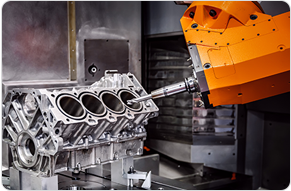
Robots and industrial machinery
-
Plant piping
-
Precision semiconductor equipment
-
Machine tools
-
Transport machinery such as rail or ships
-
Power generation equipment
-
Testing equipment
-
Utility equipment